C02 Powered Sledge Hammer
Thomas came over one night with a videotape and an excited jitter. As I watched an excited curl of hair dance about on his head, Thomas waved his arms – in a languid and frenetic way that only he can manage – and explained that he has seen, and taped, the most amazing thing: BattleBots.
His timing was excellent, because I needed another shop project. After a few months of talking about it, he, matt and I concluded that we’d try to build a weapon first, and if we could create a truly spectacular one, we’d put a chassis and wheels around it.
By extending the work on the pneumatic cannon, adding a piston and a hammer, I figured we could make something sufficiently, um, “smashy, smashy” as Thomas would say, to make a good dent in another robot. And, if it didn’t work, it would be fun to build.
My first goal was to create a piloted diaphragm valve that was not integrated with the tank, as it was in the pneumatic cannon. A separate valve would not require the a pipe to run through the middle of the tank, so the tank could have more volume, and their would be less dead volume between the valve and the piston that drove the hammer.
The value must have a large diameter – at least an inch – so that it will empty the tank quickly to the piston.
The second goal was to make a piston that is large enough to make use of the large volume of gas stored in the tank. Fortunately, I had an old nitrogen cylinder, that, at 8” diameter, would make an excellent piston body
 This first image shows the tank and the piston on the frame. The valve is hidden behind the power cylinder, and is bolted to both the tank and the bottom end of the cylinder. The tank, tank caps, valve and cylinder caps are all aluminum, and both the tank and the cylinder are held together with tie-rods.
The piston is a disc of aluminum with an oiled leather seal.
The piston drives a cable that actuates the hammer through a set of pulleys. The second image shows the test platform, with the completed pneumatic hammer after firing. The hammer moves freely on the same axle as the pulleys, and the square bar lying on the tank drives the hammer.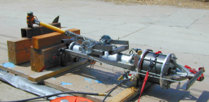
Initial testing was a lot of fun, and we put some impressive dents into the 1/4” steel target, but vexing problems surfaced immediately. The entire assembly tended to jump when it fired, and the damage the hammer inflicted was not as spectacular as we hoped. The slow firing rate and difficulty in resetting the hammer doomed this device as a battle-bot weapon, but it had a bright future as an other pneumatic cannon.
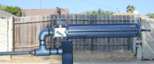 By replacing the bottom cylinder plate with a 2” pipe coupling welded to a steel plate, the hammer was easily converted to a cannon. The third image shows the completed conversion sitting on my welding side-table. The odd configuration of pipes allows easy access to the breach.
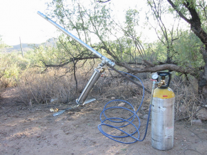 As a cannon, this design did not disappoint. The first public demonstrations naturally involved potatoes. Unfortunately, the range was poor because the potatoes would shatter when they exited the barrel. My father, brother and I spent an afternoon showering the desert with mashed potatoes. This configuration is a muzzle-loader, since the breach access pipe is the attachment point for the rear leg of the tripod.
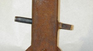
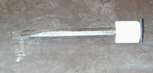 After a few more trials with mill balls and bits of plastic, we got serious. This projectile is a 1” diameter chisel. The white plastic on the back allows it to seal with a 2” pipe barrel.
Firing this projectile at 400 psi of C02 through a 10’ long , 2” diameter barrel at a 4”x4” square steel tube punctured both 1/4” sides of the tube. This result was sufficient to declare the project a success.