My Carvera bed scan project puts a cross laser on the head of my CNC, a single module that projects two lines at 90°. The laser needs power, so I cut the pigtail off the USB cable from a mouse and soldered it to the laser. That works, but you can’t turn it on or off, so the laser is always running.
This project fixes that. It’s a really cheap Raspberry Pi RP2040 in a form factor called the RP2040-Zero, which is super tiny. It sits on a small carrier board with a simple transistor circuit, and it turns the laser’s power on and off when a computer tells it to over USB.
The important thing about this project is that it’s a full Claude project. Everything is Claude’s work: the circuitry, the schematic, the circuit board, the case, and making the board.
The 3D model
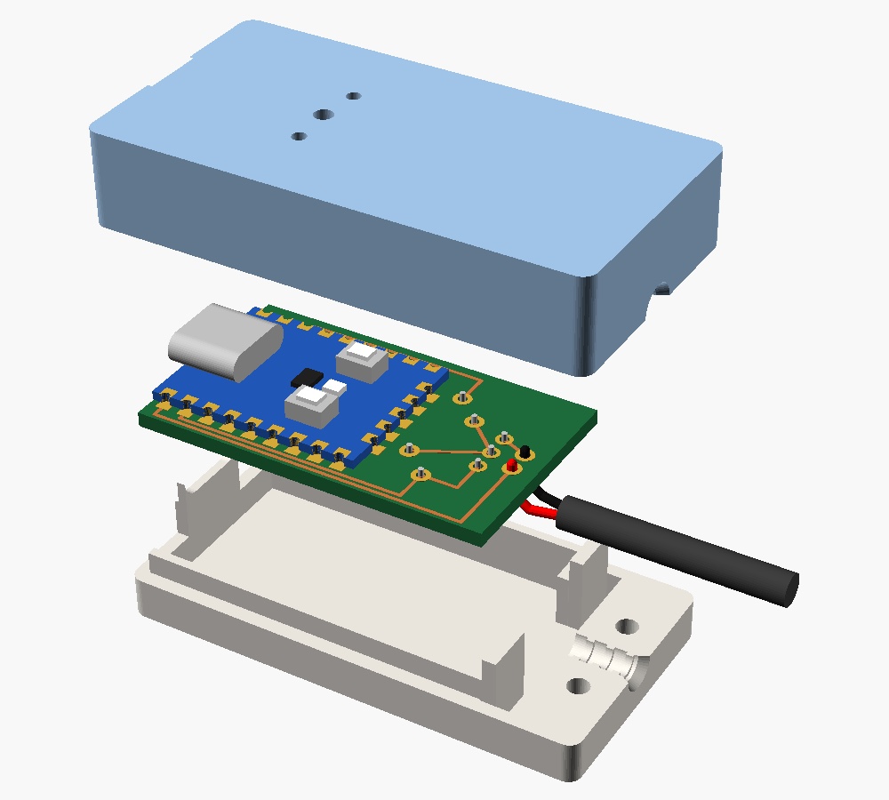
This is the complete assembly, built from one parametric OpenSCAD model. It’s interactive: you can show, ghost or hide each part, explode the assembly, cut sections through it, click a part to identify it, and take measurements.
The case comes in two versions. This one has the laser cable soldered into the board, held by a clamp with three ridges that bite into the jacket and closed with two M2 screws. The Molex version has a 2-pin header that the laser plugs into from the bottom of the case, and it’s glued shut.
The schematic
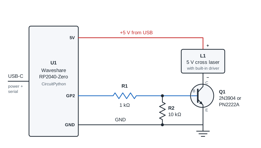
The RP2040-Zero gets its power and its commands over USB-C. The laser’s + wire stays connected to the USB 5 V, and an NPN transistor connects its − wire to ground. That’s low-side switching, and it’s the right choice here because the transistor’s base only needs to be about 0.7 V above ground, which a 3.3 V GPIO pin provides easily.
R1 limits the base current to about 2.6 mA, enough to switch around 50 mA of laser current. R2 holds the base low, so the laser stays off while the board boots or resets. The pin itself could never run the laser directly, since an RP2040 pin only supplies a few milliamps.
The board
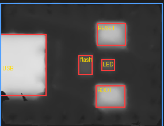
The model of the RP2040-Zero comes from a 3D scan of the real module. The top and bottom were each laid flat and turned into a height map, and the positions and heights of the USB connector, buttons, LED and chips were measured from those maps. The scanned board came out at 23.53 × 18.18 mm, matching Waveshare’s drawing of 23.5 × 18.
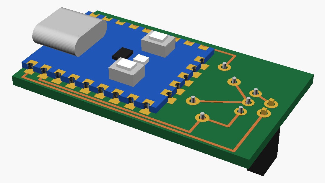
The carrier board is 39 × 23 mm, single-sided, with through-hole parts. The module solders directly to pads on the copper side using the castellated holes along its edges. All 23 get a pad, although only 5V, GND and GP2 are used, and the rest just hold the module down. The carrier is cut away under the module to make room for the parts on its underside.
Everything routes on one layer with no crossings. 5V and GND leave the module on the same side and run next to each other to the back of the board, and GP2 runs down the other side.
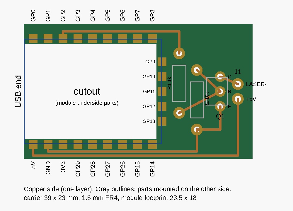
The resistors and transistor go in from the plain side and their leads come through to the copper side, so every solder joint is on the same face and the board only gets turned over once during assembly. The lid has a window over the module’s RGB LED and pinholes to reach the BOOT and RESET buttons with a paperclip.
The code
The firmware is 89 lines of CircuitPython. At startup it sets GP2 as an output,
drives it low so the laser is off, and then loops forever, checking the USB
serial port for characters every 10 ms. It builds up a line of text, echoing
what you type and handling backspace, and when you press Enter it lowercases
the line and runs the command. There are only five: on, off, toggle,
status and help.
on
laser on
status
laser on
off
laser off
The function that does the actual work is small. It sets the pin and changes the module’s RGB LED, which shows red when the laser is on and dim green when it’s off:
def set_laser(on):
    laser.value = on
    if on:
        show(40, 0, 0)
    else:
        show(0, 8, 0)
Since it’s just text over a USB serial port, anything that can open a serial port can control the laser, and that’s what the Carvera scanner needs.
The code, circuit notes, OpenSCAD model and printing tools are all in the usb-power-switch repository.