As I’ve incorporated AI into more of my workflow, I’ve gotten to feel the limitations of the traditional CAD/CAM/Controller process for machining parts, so I’ve been looking for ways to automate the process more. This project adds stereo cameras and a line laser to the Carvera CNC’s head, turning the machine into a 3D scanner for its own bed.The goal is to allow the machine to scan its bed for stock and have Claude pick the location on the stock for Z axis probing and cutting.
The goal is to not use any external software for making metal parts or laser cuts; I want to be able to just talk to Claude to design a part, review it in a 3D viewer, and send it to the CNC for cutting. I’ve already got this process for 3D printing, because my printers have a built in camera, so I want to ad those features to my CNC mill.
The 3D view below is the result. Drag to orbit, scroll to zoom, and switch between the photo-draped surface, the raw point cloud and height colours.
How it works
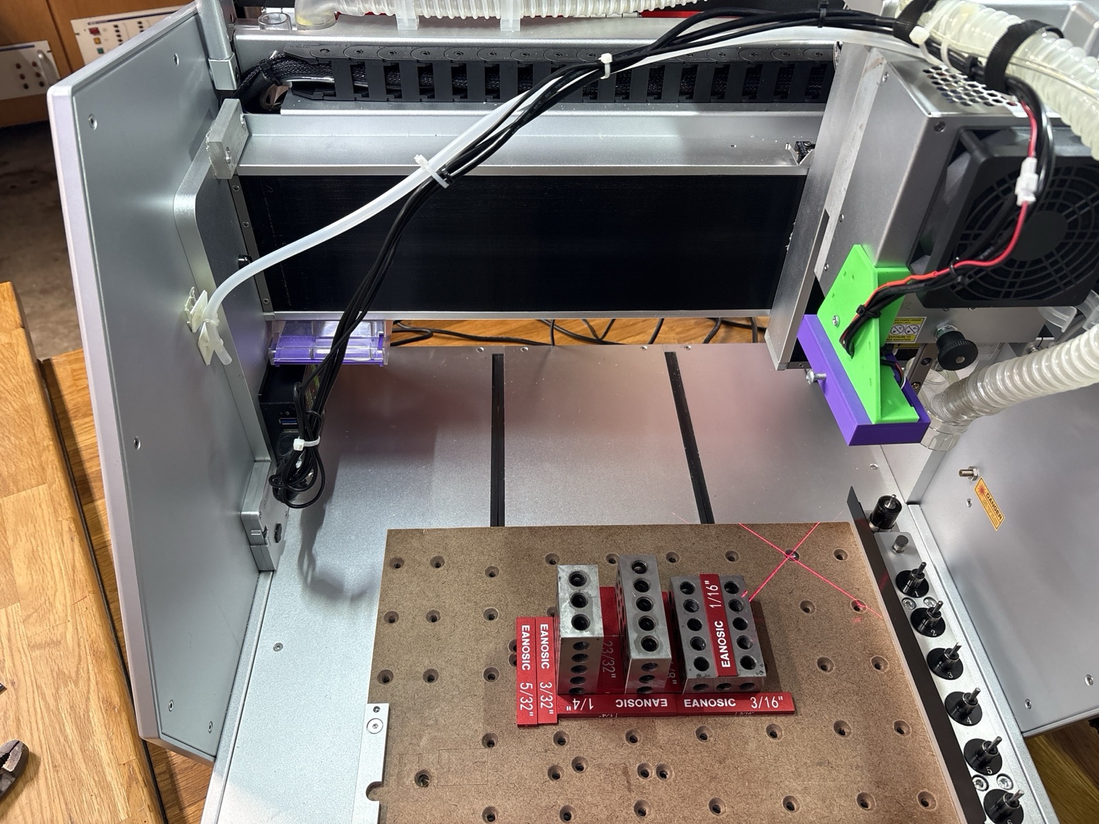
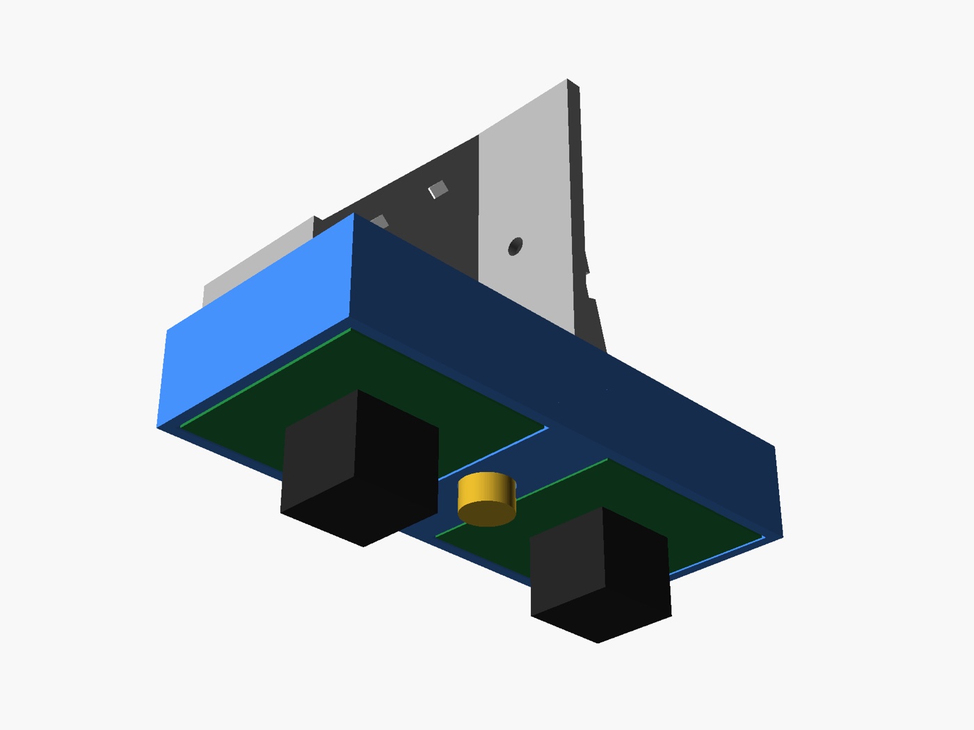
Hardware for the system is a 3D printed mount that holds the cameras and laser in place on the Carvera CNC’s head. These are USB cameras, and the laser has a USB power tether, and all three connect to a USB hub mounted inside the cabinet.
The hub is a Waveshare industrial USB 3.2 hub with two host inputs and four outputs. It runs on anything from 7 to 36 V, so I wired it into the machine’s 24 V supply. I also rearranged the Carvera’s USB ports: the output that controls the dust collector now has its own hole in the back panel, with a 4-pin connector that screws on, which leaves the rear USB-C for the controller’s UART. The USB ports on the left and right sides of the machine now feed the hub’s two inputs, so I can plug a computer into either side and run anything I want inside the machine.
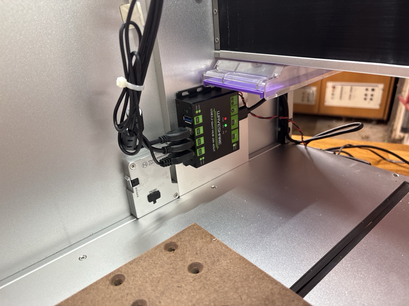
For now the cabling is temporary. My USB-C extension cables haven’t arrived yet, and the cables I have are too short, which is why the hub had to go inside the cabinet. A piece of polyethylene tubing holds the cables up so they don’t drag on the table.
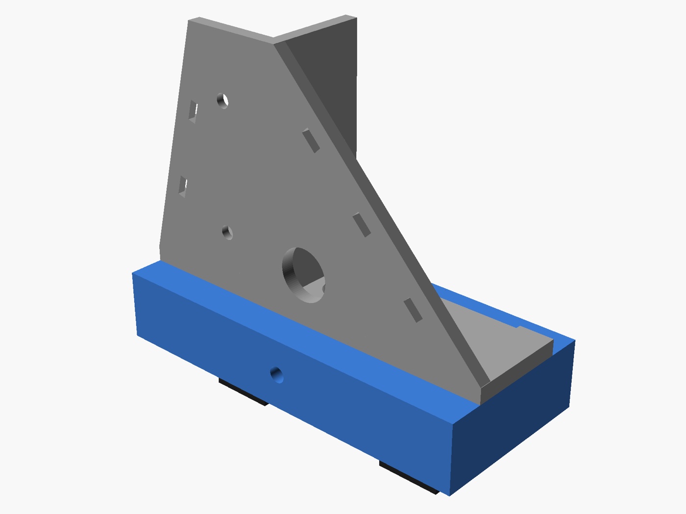
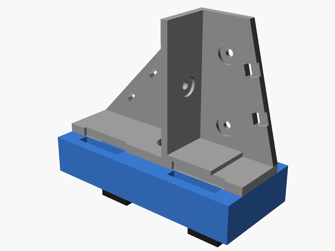
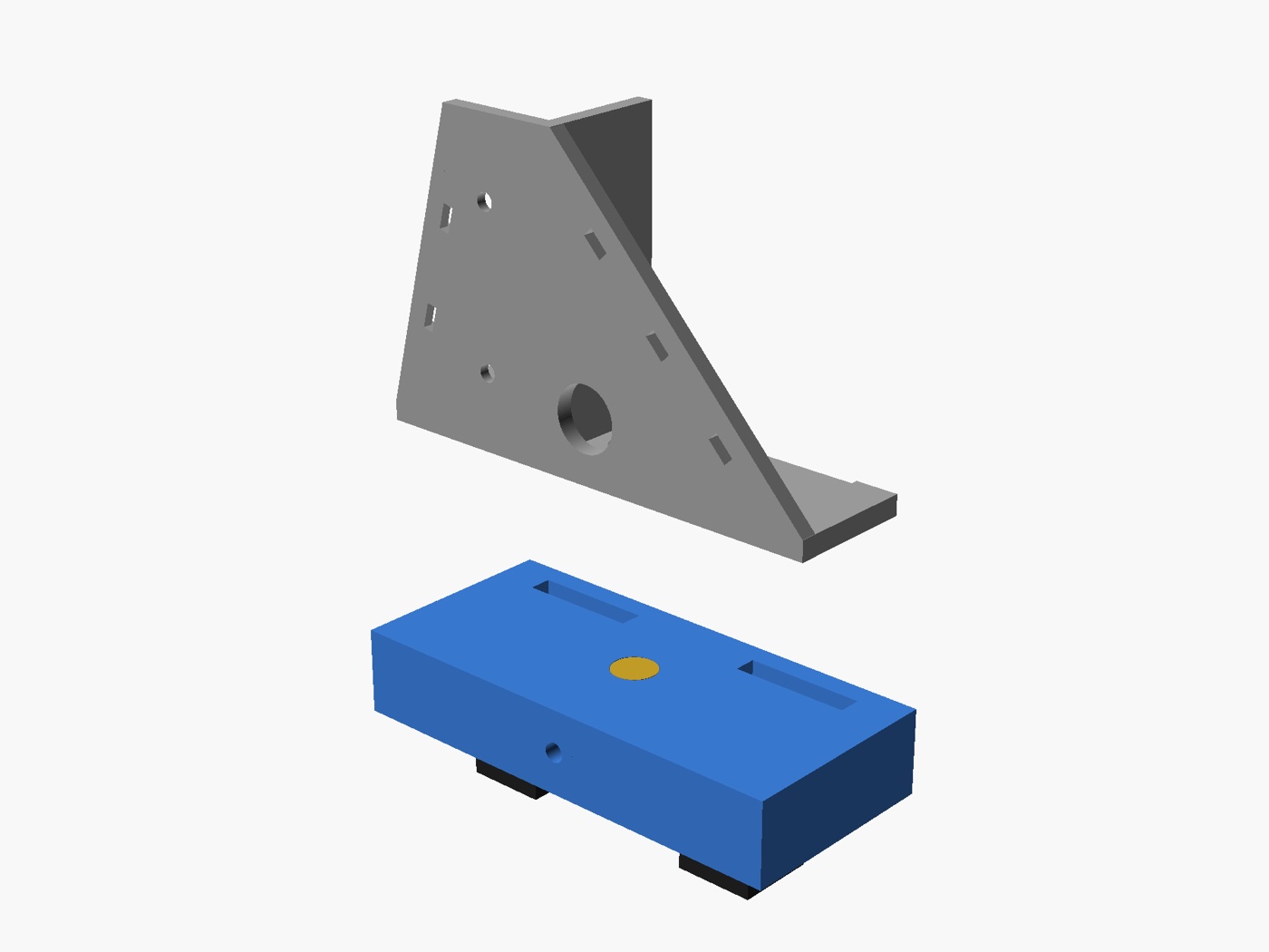
The rig is two printed parts glued together. The blue mount holds the two cameras face down, 52 mm apart, with the line laser in the rib between them. The grey bracket copies the aluminium angle that was already on the head, with the same screw holes, and grows a triangle front and back down to a glue pad along the mount’s top. A hole in the pad lines up with the laser’s bore, so a rod through both aligns the parts while the glue sets.
- Calibration from known motion. Before scanning, the head steps up and down over bare spoilboard. The machine’s Z moves give the true distance for each laser-line position, so the camera needs no separate calibration target.
- A cross of two laser lines at 45° reaches surfaces that one line would miss in shadow, and two cameras see each line from different sides.
- Sweeps. The head makes continuous passes over the bed, a quarter of a millimetre per frame, with the work light off so the line stays crisp.
- Merge and clean. Every camera and laser arm makes its own point cloud; these are merged (23 million points), checked against each other, and gridded into a 0.5 mm surface. A photo mosaic from the same cameras is draped over it.
How accurate is it?
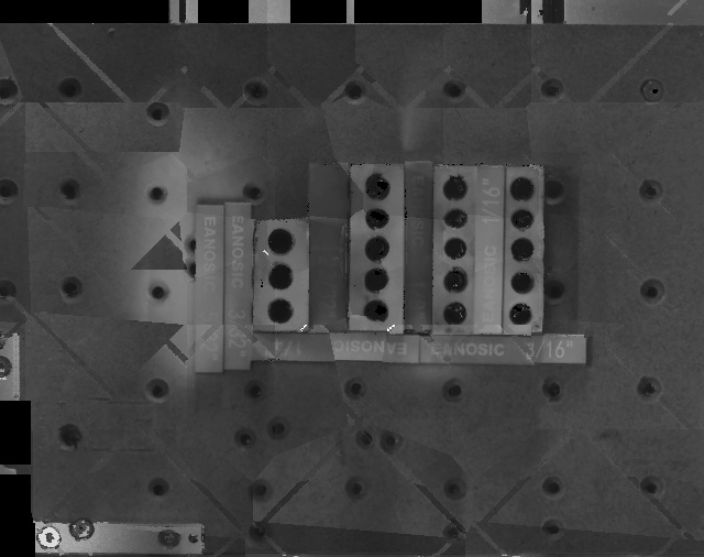
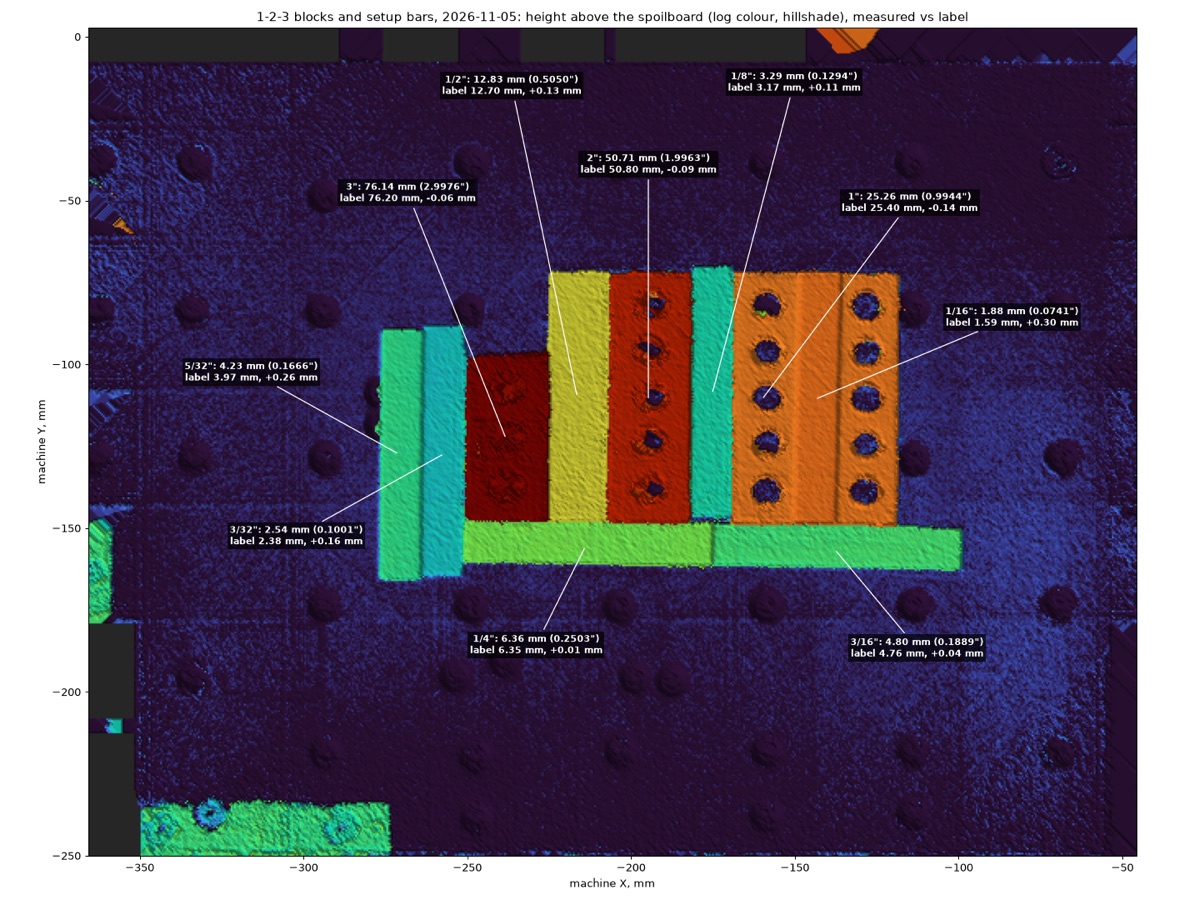
The test pieces are a set of 1-2-3 blocks and parallel setup bars, all with known sizes. Measured height above the spoilboard against the size on the label:
| Piece | Label | Label mm | Measured mm | Measured in | Error mm | Error in |
|---|---|---|---|---|---|---|
| 3" block (1x2 face up) | 3" | 76.20 | 76.14 | 2.9976 | −0.06 | −0.0024 |
| 2" block (1x3 face up) | 2" | 50.80 | 50.71 | 1.9963 | −0.09 | −0.0037 |
| 1" block (2x3 face up) | 1" | 25.40 | 25.26 | 0.9944 | −0.14 | −0.0056 |
| 1/2" bar | 1/2" | 12.70 | 12.83 | 0.5050 | +0.13 | +0.0050 |
| 1/4" bar | 1/4" | 6.35 | 6.36 | 0.2503 | +0.01 | +0.0003 |
| 3/16" bar | 3/16" | 4.76 | 4.80 | 0.1889 | +0.04 | +0.0014 |
| 5/32" bar | 5/32" | 3.97 | 4.23 | 0.1666 | +0.26 | +0.0103 |
| 1/8" bar | 1/8" | 3.17 | 3.29 | 0.1294 | +0.11 | +0.0044 |
| 3/32" bar | 3/32" | 2.38 | 2.54 | 0.1001 | +0.16 | +0.0064 |
| 1/16" bar (on 1" block) | 1/16" | 1.59 | 1.88 | 0.0741 | +0.30 | +0.0116 |
Height above the spoilboard (the 1/16" bar: above the 1" block it lies on), the median of four camera/laser-arm combinations, each measured against its own bed plane.
The blocks and the thicker bars come in within about 0.15 mm. The thin bars read high, probably because they were not lying quite flat on the bed.
What’s next
Turning the scripts into a package that runs the whole scan from the machine, and using the scans to find and measure stock before cutting.